

Floating Suction Pressure: The Highest-ROI Control Strategy in Supermarket Refrigeration
Controlling suction pressure on a supermarket refrigeration rack is one of the most effective yet under-used strategies in the field. If you still hold a fixed conservative suction set-point and ignore floating logic, you’re likely leaving substantial energy savings on the table. Let’s dive deep into how floating suction works, why it delivers meaningful savings, how to implement it properly, and how to avoid the pitfalls — all written for the technician who must make it work in the real world.
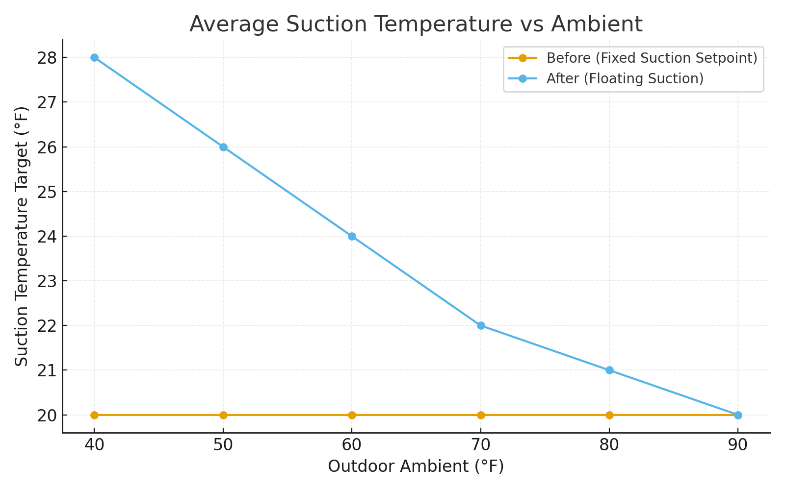
What “floating suction” actually does (and why it saves so much)
On a typical multiplex rack system, “floating suction pressure” refers to letting the evaporating pressure (and hence suction temperature) increase when the warmest case in a group still holds its set-point—and only pulling suction pressure down when that case starts to trend toward its limit. In practical terms: instead of holding a fixed (often conservative) suction temperature year-round, you continuously raise the suction set-point as long as your critical case is within margin. When the case moves out of margin, you reduce suction to protect it.
Why does this matter? Because compressor work is directly tied to the compression ratio — the difference between condensing pressure and evaporating pressure. When you raise the suction (evaporating) pressure, you reduce the lift and thereby reduce the energy required per ton of refrigeration. You also cut runtime because the compressor sees less load and often cycles less aggressively.
Field results confirm this: many supermarket systems see 10-30 % reduction in rack energy once floating suction is properly implemented. For planning purposes, a rule of thumb often cited is about 2 % reduction in compressor power for every 1 psi increase in suction pressure, or similarly about 2 % efficiency gain per °F increase in suction temperature. Every little lift reduction counts.
In one real-world case, increasing saturated suction temperature by just 3 °F yielded about a 4 % reduction in energy usage on a multi-compressor rack. Those savings scale up when the baseline is less optimized, heads are floating, and cases are tuned. Bottom line: floating suction isn’t a marginal tweak—it can be a major lever in the refrigeration system control suite.
Control concept: “warmest-case wins”
Getting floating suction right requires good control logic and good case monitoring. The general concept is this:
Your rack controller monitors the temperature of each case (most effective: return-air from each case), or alternatively it monitors evaporator outlet/superheat for each branch.
The logic identifies the “limiting” case — i.e., the one that is closest to its set-point limit or showing the highest delta from set-point.
As long as all cases in that suction group are maintaining their targets comfortably, the controller will step up suction set-point slowly, raising the evaporating temperature/pressure.
If one case begins to drift toward its set-point limit (or a superheat threshold), the controller reduces the suction set-point to protect that case.
The control loop uses rate limits (how fast suction set-point can change), deadbands (to avoid hunting) and upper/lower bounds (to avoid compressor or valve issues).
In effect, the controller gives priority to the warmest case, letting it lead the group. If that case still has margin, the whole group can float to a higher suction and deliver improved efficiency.
This logic is present in most modern rack controllers, and leading OEM and control-system documentation recommend floating suction as a best-practice for supermarket racks.
Practical set-points and bounds (MT & LT)
Floating suction doesn’t mean “let it float wild.” You still define a safe operating window:
Medium-Temperature (MT) group: Typically, suction temperature might start at the conventional fixed set-point (say +18 °F SST equivalent), and you may float up to maybe +23-25 °F SST equivalent (depends on cases and design). Exactly where depends on your case coils, EEVs or TXVs, compressor design, and defrosts.
Low-Temperature (LT) group: Because LT systems inherently have bigger lift and lower evaporating temps, the potential relative gain is even larger—but you must be careful. Set a minimum evaporating temperature (often per compressor envelope) and a maximum that still ensures defrosts, frost management and fan/case performance are unaffected.
While floating, you must also ensure superheat control remains stable, that coils are fully utilized (no floodback risk), and that compressor cooling and lubrication remain safe. Many compressor manufacturers list limits on minimum evaporating temperature, especially for lubrication and discharge line temperatures. Always verify those limits.
The bottom line: define your minimum suction bound (current set-point) and a maximum suction bound (based on warmest-case margin under low load/run hours) and let the system float within that range. You’ll typically pick small increments (1-3 °F at a time) upward and small decrement steps downward when needed.
Case control details that make or break results
Floating suction will only deliver results if the rest of the refrigeration system is tuned and stable. Here are the key areas the technician must address:
1) Use the right temperature reference.
We recommend case return-air sensors rather than supply or discharge sensors. Return air tracks product temperature more reliably and is less affected by coil frost, fan speed changes, or supply air variations. If return-air sensors are inaccurate, you lose the critical feedback loop.
2) Tighten case controllers and valve authority.
If case controllers have too much hysteresis (wide error band), or EEVs/TXVs are poorly tuned, your “critical case” will oscillate and induce rack hunting rather than smooth float. Adaptive superheat control helps: it ensures your evaporators are fully loaded (maximize heat transfer) and protects against flood-back while floating to higher suction.
3) Fix airflow and defrost behavior first.
If one of your cases has poor airflow, a fan failure, or abnormal defrost operation, that case often becomes the critical one and prevents floating. Before enabling floating suction, ensure cases have clean coils, proper fan operation, correct defrost schedule and a stable under-case return-air baseline.
4) Coordinate with EPR/EEPR (evaporator pressure regulators) if applicable.
If you still use mechanical EPRs at each case or branch, make sure they aren’t overriding the rack suction set-point. With electronic EPRs or electronic expansion valves (EEVs), make sure the rack control is given priority over individual case pressures and that the control zones don’t fight each other. Essentially: rack suction logic must own the float; cases must follow.
Once the cases are functioning well, floating suction becomes more stable and your savings are repeatable.

Interactions to watch (floating head, heat reclaim, CO₂, 2-stage racks)
Floating head pressure
Floating head (letting condensing pressure drop when ambient conditions permit) is another high-value control lever. Floating head + floating suction = reduced total lift (evaporator to condensing). But you must coordinate: if head pressure drops too far, piping or valve issues (TXV, EEPR) may show up. Make sure you maintain a head-pressure minimum if needed by the system design. Floating head also reduces fan power and condensing fan runtime in many systems.
Heat-reclaim systems
If your store uses heat reclaim (for HVAC pre-heat or domestic hot water), be careful: floating suction (and floating head) will raise suction temps (and possibly reduce condensing temp), which may reduce available reclaim capacity. Your control logic must prioritize: are you saving rack energy or maximizing reclaim? In many cases you do both, but you should document the trade-off and possibly have logic that prevents floating suction from interfering when reclaim demand is high.
CO₂ booster racks / Transcritical systems
Floating suction remains a valid strategy in CO₂ systems, but the behavior differs: transcritical racks, parallel compression racks, and cascade systems have different component boundaries and control limitations. Case-coil and branch valve authority, compressor motor cooling, and compressors’ operating envelopes all behave differently. If you work with CO₂, coordinate with the OEM’s guidance for maximum evaporating temp / suction pressure rises.
Tuning workflow we use in the field
Here’s a step-by-step approach for technicians to implement floating suction:
Step 1: Pre-checks
Verify accuracy of all case return-air temperature sensors (swap or ice-bath tests).
Confirm rack compressor envelope (minimum evaporating temperature, max suction temp, etc.).
Clean coils, verify airflow, ensure defrost schedule is correct.
Step 2: Choose a safe starting window
Set minimum SST (suction temperature) equal to your existing fixed set-point.
Choose a maximum SST approx. 3-6 °F higher (for MT), or 2-4 °F higher (for LT), as a conservative starting point.
Set ramp rate (e.g., increase 0.5-1.0 °F per 5-10 minutes) and deadband (e.g., ±0.5 °F) so the suction logic doesn’t chase noise.
Step 3: Enable warmest-case logic
Configure the rack controller to monitor each case’s return-air error (actual minus set-point).
The logic should identify the “warmest” case (largest positive error).
If that error remains negative (all cases are within margin), the suction set-point floats up. If the error becomes positive, the suction set-point steps downward.
Step 4: Walk the window upward during low load
During nights or shoulder seasons when load is lower, observe how high you can raise the suction set-point without any case reaching its limit.
Monitor compressor amps, discharge temperatures, valve positions, and logging of kW/ton.
Stop increasing when you see the first case approach tolerance (e.g., 0.5 °F below set-point or superheat margin decreases).
Step 5: Verify valve authority and superheat
On the limiting case, check the EEV/TXV is not at full open all the time (that signals you’re at the coil limit).
Make sure superheat is stable and within spec; using adaptive superheat gives you better margin.
If case performance is weak, you may need to improve coil/airflow or reset that case’s parameters.
Step 6: Baseline and M&V (Measurement & Verification)
Before floating, capture baseline run-hours, kW, kW/ton, and case return-air deltas for representative weeks.
After floating, measure the same metrics and compare. Use normalization (weather, hours, case load) to confirm savings. If you need program-quality savings (for incentives), follow recognized methods such as ASHRAE Guideline 14.
What savings should you expect?
While each store is unique, here are realistic expectations:
Many supermarket racks show 10–30 % reduction in rack energy once floating suction is properly implemented and tuned.
In planning mode: you can estimate ≈ 2 % compressor power reduction per 1 psi suction increase (or roughly per 1 °F SST increase) as a ballpark—but always validate your specific system.
For example, raising SST by just 3 °F delivered ~4 % energy reduction in a documented case.
The actual magnitude of savings depends on: baseline set-point (how conservative you were originally), how much of the load is LT vs MT, how optimized the case controllers and EEVs are, and whether other controls (floating head, night-curtains, defrost) are already in place.
Savings aren’t just about energy. By reducing load and compressor cycling, you also extend equipment life, reduce maintenance, and stabilize case temperature — all contributing to better reliability, product quality and lower shrink.

Common pitfalls we fix again and again
Technicians often implement floating suction and then wonder why the savings haven’t materialized. Here are the most frequent causes and how to avoid them:
Bad case probe or sensor wiring: When one case sensor reads warm even though the product is fine, it becomes the limiting case and prevents the rack from floating. Solution: verify and calibrate every sensor used in the logic.
Using supply air temperature instead of return: Supply temperatures change dramatically when airflow or coil frosting varies; return-air is a better indicator of product and case performance.
Mechanical EPRs set too high or inconsistent: If an EPR or EEPR is maintaining a lower suction in the branch than the rack set-point calls for, you won’t realize the higher suction. Solution: coordinate and document which control owns suction.
Too aggressive rate of change: If the suction set-point floats too quickly, you’ll trigger hunting, outages, short-cycling, and unstable superheat. Solution: implement conservative ramp-rates and deadbands.
Ignoring compressor or component limits: Some compressors require minimum evaporating temps or minimum suction pressures for lubrication and discharge safety. If you float beyond those limits, you risk damage. Always consult OEM envelope.
No coordination with defrost, reclaim, or other controls: If you enable floating suction without checking defrost system timing/fan performance/heat reclaim demand, you may reduce margin and trample savings.
No baseline or M&V plan: Without credible baseline data and measurement after implementation, you won’t know if you truly saved anything—and you may lose credibility with stakeholders.
Why floating suction is a sustainability lever (not just a bill reducer)
From a sustainability and energy-management perspective, floating suction checks a lot of boxes:
Lower kWh and reduced kW at the rack means lower Scope 2 emissions (for electric utilities) or Scope 1/Scope 3 where applicable.
Reduced cycling and lower lift mean less wear & tear on compressors, which improves equipment life and reduces lifecycle carbon/hardware replacement footprint.
Stabilized case temperatures help improve product quality and reduce spoilage/shrink, adding indirect savings and sustainability benefits.
With many stores transitioning to lower-GWP refrigerants and complex rack systems (parallel compressors, CO₂ boosters, heat reclaim), floating suction is a control strategy that extracts maximum value from that investment rather than relying solely on refrigerant change.
In short: floating suction makes your refrigeration system work smarter, not just harder, and aligns energy efficiency, reliability and sustainability in one move.
Bottom line from Northstar
If you still run your supermarket rack with a fixed, conservative suction setpoint, you’re most likely under-utilizing one of the highest-ROI control strategies available: floating suction pressure. Commission this strategy properly, and you’ll typically capture double-digit pack energy savings, improve case stability, extend equipment life—and earn a credible story for your energy management program. Start by ensuring your case sensors and valves are tuned, define a safe floating window, adopt “warmest-case wins” logic, and baseline before you adjust. This isn’t a one-time tweak—it’s a strategic control layer that should be part of your refrigeration-EMS roadmap.
Ready to dive deeper?
For technicians eager to elevate their store’s performance further, I’m writing a new book titled “Supermarket EMS: Controls, Commissioning & Sustainability” which will deliver step-by-step frameworks, field-tested tuning workflows, case-study guided diagnostics and energy tracking tools for supermarket refrigeration systems. Want a free chapter preview and early-bird discount when the book launches? Click here → Download your free preview and I’ll add you to the pre-launch list.
Thanks for reading. Stay curious, keep commissioning, and let’s make supermarket refrigeration smarter and more sustainable together.